30초 요약
Andy Ray introduces FPGA design and HardCaml, the OCaml library he developed for describing hardware. He walks through simulation, waveform testing and formal verification, then demonstrates an OCaml bytecode stack on a MicroBlaze FPGA system. In the discussion he addresses limitations, generated Verilog, soft CPU uses and possible future directions.
- 1OCaml nearly all the way downHardCaml describes hardware and OCaml drives embedded software, but the demonstration still relies on a vendor CPU and backend tools.
- 2Hardware as a graphHardCaml represents registers, memories and operations as OCaml data, with wires allowing cycles.
- 3Concurrent hardware testsThe step test bench coordinates independent tasks and can integrate a MicroBlaze instruction-set simulator with a hardware design.
- 4Prove by searching for a counterexampleA SAT solver checks the negation of a property: UNSAT proves it for the modeled inputs, while SAT supplies a failing assignment.
- 5OCaml on a soft CPUThe demo cross-compiles the OCaml runtime for MicroBlaze and packages bytecode and C stubs into an executable.
- 6Generated Verilog remains a tradeoffThe backend consumes generated Verilog, which Ray says is difficult to read; naming registers helps interpret timing reports.
핵심 정리
- FPGAs combine configurable lookup tables and routing with registers, block RAM, DSP and other specialized resources.
- HardCaml represents a hardware design as an OCaml graph and generates Verilog for vendor backend tools.
- Cycle simulation, concurrent test benches, waveform expect tests and SAT-based checks address different verification needs.
- OCaml bytecode and libraries can run on a MicroBlaze soft CPU using a cross-compiled C runtime, with significant size and platform limitations.
- The soft CPU can support control and debugging, while the performance-critical path remains in hardware.
챕터별로 다듬은 전문 읽기
A blinking FPGA and the design
Ray introduces the demo, its soft CPU and HardCaml peripherals. He explains what the bootloader and LEDs are doing.
The title contains a lie: this is not quite OCaml all the way down. We can design FPGA and ASIC hardware in the HardCaml domain-specific language and write embedded software in OCaml, but this demo uses a vendor's soft CPU rather than one designed in HardCaml. The back-end place-and-route tools are also the vendor's.
The first demonstration blinks LEDs. You might think that takes ten lines of Verilog; I prefer to call it 200,000 lines of OCaml. Resetting the FPGA loads a design with a MicroBlaze CPU, 256 MB of DDR3 memory and a timer, as well as a HardCaml design connected to the CPU through a bus and register interface.
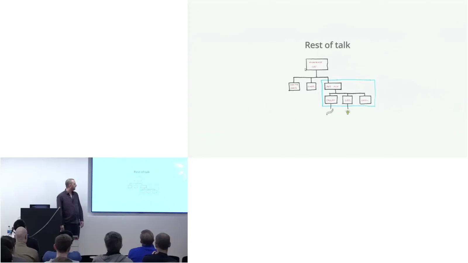
That design connects three cores: a DigiLED driver for the strip, an SPI interface for a light sensor, and a CORDIC core. CORDIC computes functions such as sine, cosine and hyperbolic functions using additions and shifts. A custom bootloader loads a program from SPI flash into DDR memory; the blinking LEDs indicate its progress as it loads blocks of roughly 64 KB.
How FPGAs work
An overview of LUTs, routing, RAM, DSP, clocks, configuration and hard blocks. These resources make programmable hardware practical.
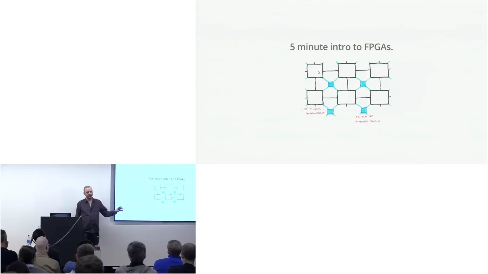
An FPGA can be thought of as a grid of lookup tables (LUTs) and registers, connected by fast local routing. Switch boxes connect LUT outputs to global routing resources that can carry signals across the chip. This is an abstraction, but it gives a useful picture of the fabric.
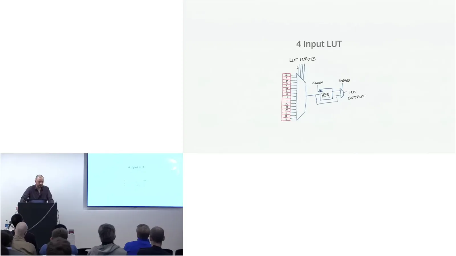
A four-input LUT can be built from 16 static RAM cells whose contents are set when the FPGA loads. Its inputs select one cell, so it can implement any four-input Boolean function. Set all cells to zero except the last and you have an AND; reverse that pattern for an OR. Modern devices often use six-input LUTs. An optional register captures the result, or can be bypassed for larger combinational functions.
FPGAs also have block RAM, ranging in the examples I discuss from about 10 kilobits to 288 kilobits per block, with hundreds to tens of thousands of blocks on modern devices. Their combined bandwidth can be enormous. Dedicated DSP blocks provide multipliers and related arithmetic, while clocking resources derive and distribute clocks with different frequencies and phases.
Configuration commonly comes from flash, and USB interfaces make it convenient to program a board from a PC. The I/O pins are complex resources in their own right. Vendors also add hard silicon blocks for functions such as PCIe and Ethernet, and some FPGAs include ARM processor cores.
RTL languages and verification
Ray explains combinational and clocked logic, event-driven Verilog, simulation tools and property checking. He contrasts simulation traces with formal proofs.
RTL design sits near the bottom of a hierarchy of abstractions. It combines combinational logic such as adders and encoders with clocked elements such as registers and RAM. Soft CPUs bring embedded programming, instruction sets and operating systems into the picture too; a programmable state machine can have its own instruction set, even without a conventional CPU.
The main RTL languages are VHDL, Verilog and increasingly SystemVerilog. SystemC is primarily a modeling language, while other tools try to turn untimed C into hardware, with varying results. These hardware languages were originally conceived as documentation languages. Their event-driven semantics take some getting used to.
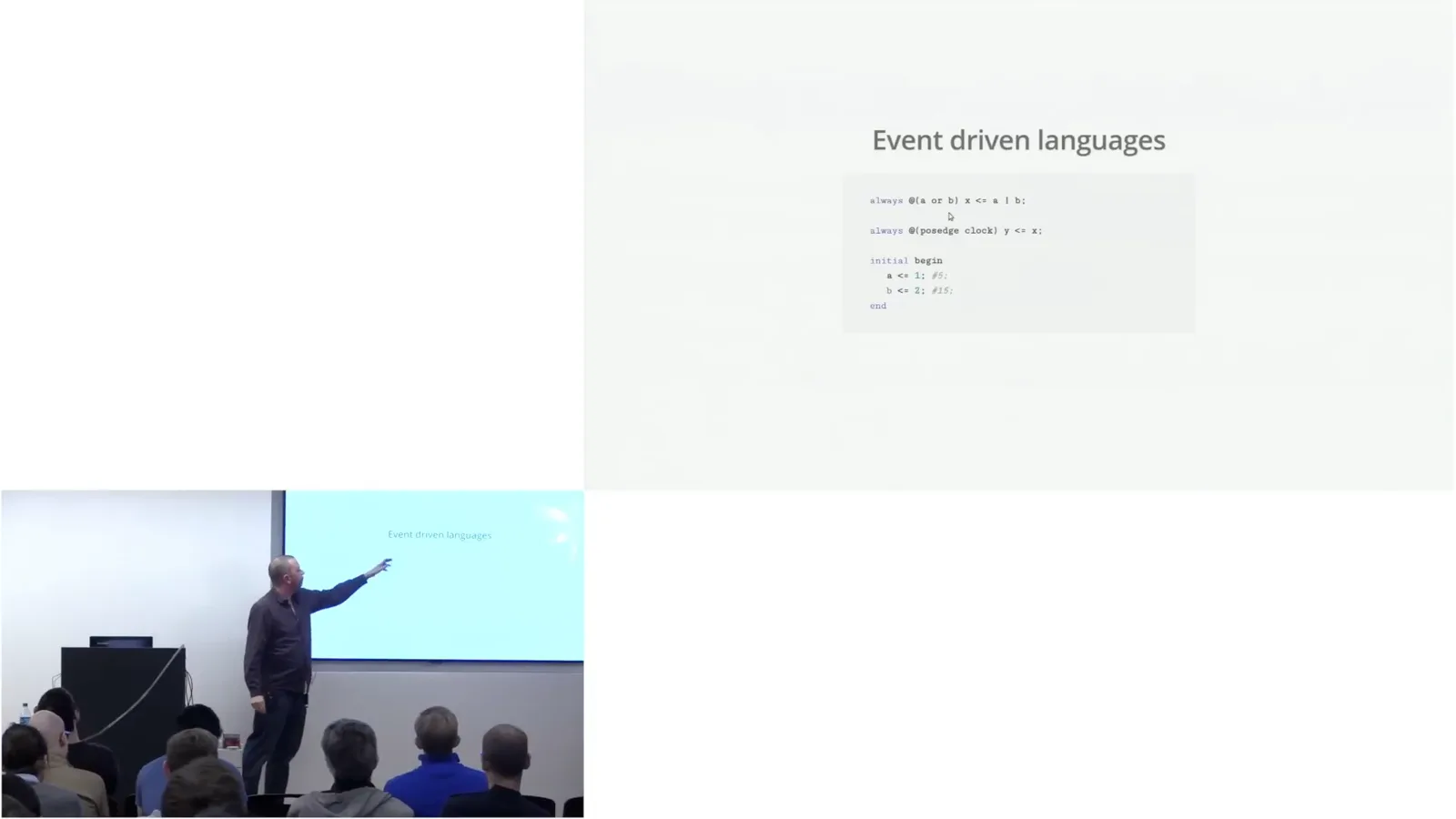
In Verilog an always block may update an output when an input changes, describing combinational logic. A block sensitive to a clock's positive edge instead loads a register once per cycle. RTL is passive, so a test bench generates changes and delays to exercise it. Those event-generating constructs are for simulation, not synthesis into hardware.
Commercial simulators include ModelSim and VCS; open-source options include Icarus Verilog and GHDL. Verilator converts synthesizable Verilog into an optimized C++ model and can be very fast. At the time of this talk, I see a gap in open-source SystemVerilog simulation support, especially as vendors move their IP to that language.
RTL debugging often means looking at waveforms: signal transitions plotted over time. Even a small simulation produces a busy display, and real designs can be enormous. Constrained random stimulus and coverage-driven frameworks help exercise interesting parts of a design, such as the supported packet protocols of a network core.
Temporal assertions can check that, for example, one event follows another within five clock cycles. Simulation checks properties on the traces it runs; formal verification tries to prove properties for every trace. That is the really interesting part, even if the machinery feels like black magic.
The HardCaml representation
Hardware becomes a cyclic graph of OCaml values. The API supports bit vectors, sequential primitives, state machines and vendor IP.
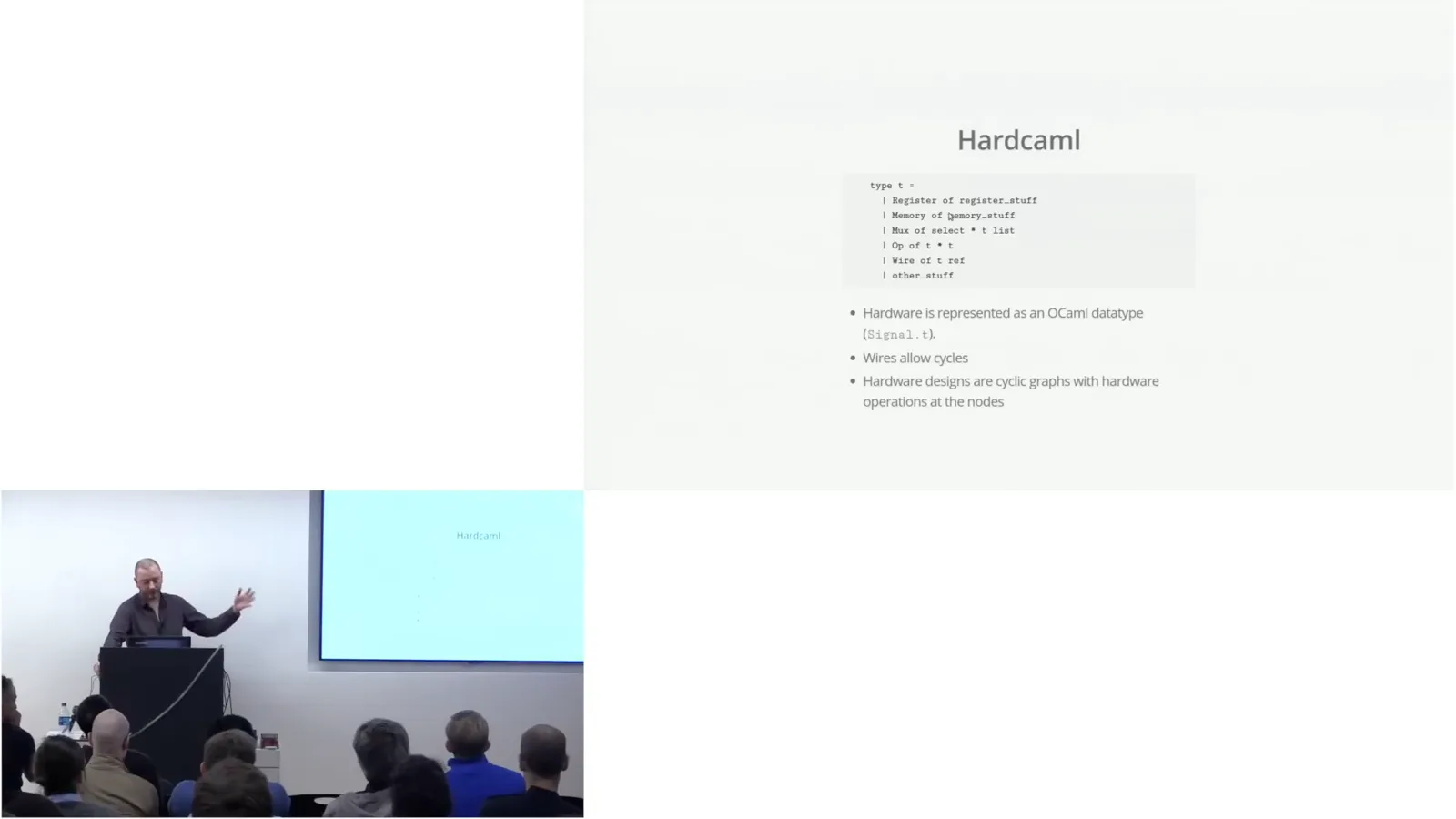
At its heart HardCaml represents hardware as an OCaml data structure with nodes for registers, memory, multiplexers and operations. It resembles a compiler AST, but wires can be created and used before being assigned, allowing cycles. It is more useful to think of the design as a potentially cyclic graph of hardware nodes and connections.
The core API offers arithmetic, logic, comparisons, constants and multiplexers over bit vectors of arbitrary widths. A design can query the width of a signal and construct logic that adapts to it. Instantiation also lets us leave a hole in the HardCaml graph for third-party Verilog or VHDL, vendor primitives or macros.
Operators distinguish unsigned or sign-independent operations from those where signedness matters, such as multiplication and comparison. Many checks happen at elaboration time, when the graph is constructed, not when the hardware runs. The API is strict about widths: adding a two-bit value to a three-bit value, for example, raises an error.
The API operates over two representations. Bits compute values directly, while signals record the computation. We use signals to describe the hardware graph and bits to drive concrete values into its ports during simulation.
HardCaml's sequential primitives are registers and an asynchronous-read memory. Higher-level structures, including state machines, are built on them. The always DSL resembles Verilog always blocks: guarded conditions, if statements and switches determine assignments to registers or combinational values. We use it especially for state machines and their next-state logic.
Registering a memory's address or output produces different read/write behaviors that vendor tools should infer, although inference does not always succeed. Some structures, including a true dual-port RAM, require vendor macros; that issue also arises with Verilog.
FIR filter and hardware testing
A filter illustrates the design API. Cycle simulation, concurrent test benches and waveform tools help test and debug hardware.
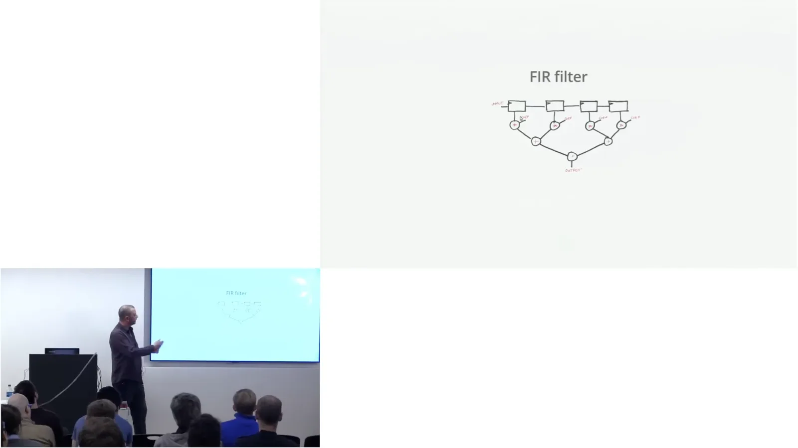
My hardware hello world is a finite impulse response filter. Four registers hold a moving window of the last four samples. Each sample is multiplied by a constant coefficient, and a balanced tree adds the results. HardCaml builds the register window as a list, maps signed multiplication over it and reduces the results with a reusable tree function.
HardCaml provides cycle-accurate simulation, rather than event-driven simulation. Build the simulator, set input ports, advance one cycle, read outputs and repeat. That works for simple designs, but hardware may have several independent interfaces, such as FIFOs, registers and memory, which makes a single flow of control awkward.
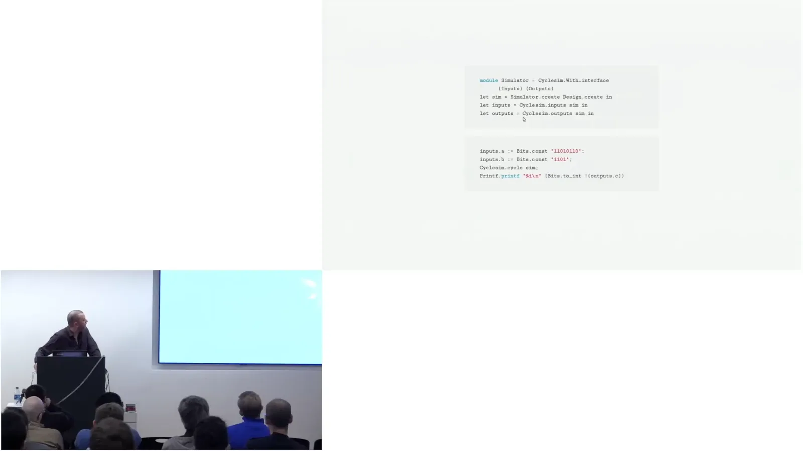
HardCaml's step test bench is roughly Async for hardware testing: multiple independent tasks can drive different interfaces and still communicate. We integrated it with a MicroBlaze instruction-set simulator, written by Mark. It loads a MicroBlaze ELF program and runs it at a few megahertz while interacting with simulated hardware over a standard bus such as AXI.
For debugging I wrote an interactive terminal waveform viewer. HardCaml can also produce standard VCD files for viewers such as GTKWave, or stream simulation data to GTKWave as it runs. Waveform expect tests put the expected waveform in the test itself, so continuous integration can show a diff when behavior changes.
Text waveforms become unwieldy after perhaps 30 cycles, but they are useful for documenting small protocol details that should remain stable. When a test changes, the diff makes it clear that something needs attention.
SAT and formal verification
Ray describes proof by negation, equivalence checking and bounded model checking. He states the limits of his experimental checker.
Consider proving a ten-bit adder correct. Its two inputs make 20 input bits, or about a million test cases; exhaustive testing becomes impractical at 200 bits. A SAT solver instead looks for an input assignment that makes a Boolean function true. If such an assignment exists, it returns SAT and the values; if none exists, it returns UNSAT.
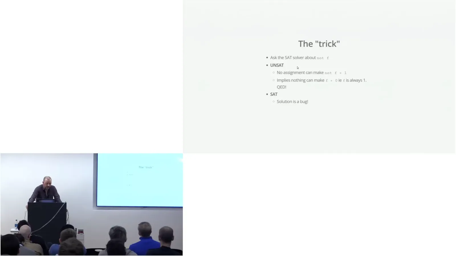
To prove a property always holds, ask the solver about its negation. UNSAT means there is no input that makes the negation true, so the property holds; SAT supplies a counterexample showing where it fails. HardCaml can turn a one-bit property over a combinational circuit into a SAT problem.
We also have a framework for sequential equivalence checking. To verify a Verilog-to-HardCaml port, I used Yosys to turn the Verilog into a low-level netlist, loaded that into HardCaml and asked whether the outputs always match. This method requires registers in corresponding places in both circuits.
Bounded model checking can compare circuits with different states over a fixed trace, using temporal properties. A proof over 100 cycles says nothing about cycle 101. My checker works on small cases, although I do not yet fully trust it; even with the bound, the technique is powerful.
The embedded OCaml stack
An OCaml bytecode interpreter and libraries run on MicroBlaze. Ray describes cross-compilation, missing platform features and executable size.
The software stack runs on MicroBlaze, a Xilinx soft RISC CPU built from FPGA fabric. There is no native OCaml compiler for this architecture, but a GCC cross-compiler exists. I cross-compiled the OCaml C runtime and its Zinc bytecode interpreter, then used ordinary x86 builds of the bytecode libraries, even though the target is 32-bit.
The OCaml `-output-obj` option produces a C file containing the program bytecode as an integer array, which the cross-compiler can compile. The tricky part is finding, compiling and linking the C stubs used by the OCaml libraries; I found around 40 C files in all.
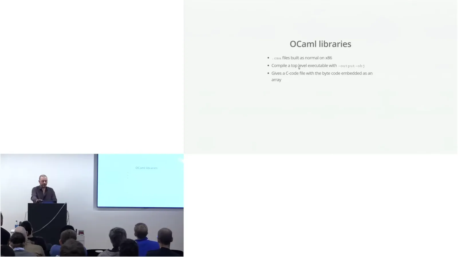
Signals and threads do not work in this setup, and there is no filesystem or Unix environment. An RTOS might offer threads, though I am unsure whether they would match OCaml's expectations. Base, Core_kernel and Async_kernel do work, as does the OCaml top level: the compiler itself runs on the FPGA.
The cost is size. The smallest executable is about 400 KB; adding Jane Street libraries brings it to roughly 700 KB, with more features quickly reaching 4–5 MB. The top level with these libraries totals about 23 MB: it cannot discard potentially usable code, and the CMI files used for type checking occupy roughly 16 MB.
Live demonstrations
The OCaml top level drives LEDs, a light sensor, a CORDIC core and concurrent Async tasks. Ray discusses plans for releasing the tools.
In the live top-level demo, the processor's standard input and output travel over USB to a laptop driver, which bridges them to a TCP socket; I connect with netcat. When I enter `let a = 1`, OCaml running on the FPGA compiles it and displays the result.
The pulse-width modulation demo turns LEDs on and off rapidly so they appear to have intermediate brightness. Varying that brightness makes them breathe. The Cylon demo moves a light back and forth along the strip, with a busy loop to slow it down and a pass that halves each LED's intensity to leave a fading tail.
A light-sensor Pmod is read through SPI: start a transfer, wait for completion and read the result. The lower four bits are discarded and the next eight contain intensity. I am not sure whether the noisy readings reflect flickering lights or sensor accuracy, so the demo averages about 500 readings and displays the result on the LED strip.
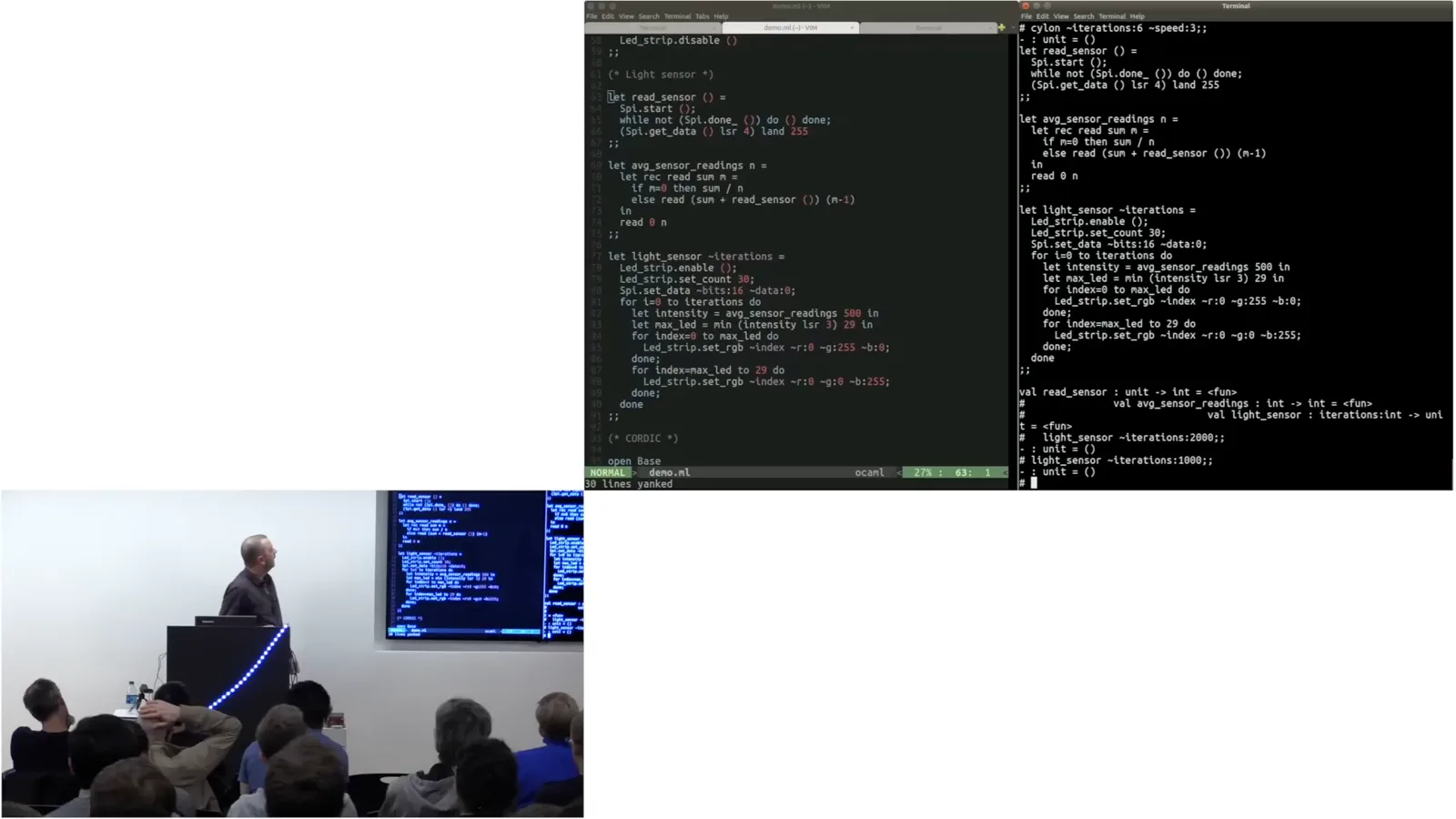
An audience member asks about the LED driver. Mark wrote the DigiLED driver in HardCaml. A single line carries pulse-width-modulated bits for the RGB values; the driver programs the LEDs in sequence along the strip.
Another demo uses the HardCaml CORDIC core to calculate cosine. The core can also compute functions such as arctangent, hyperbolic functions and coordinate rotations. It computes sine and cosine together; I configure its inputs, set the angle and wait for completion. Because convergence is limited to roughly minus pi over two through pi over two, the code reduces the angle and uses quadrant symmetry.
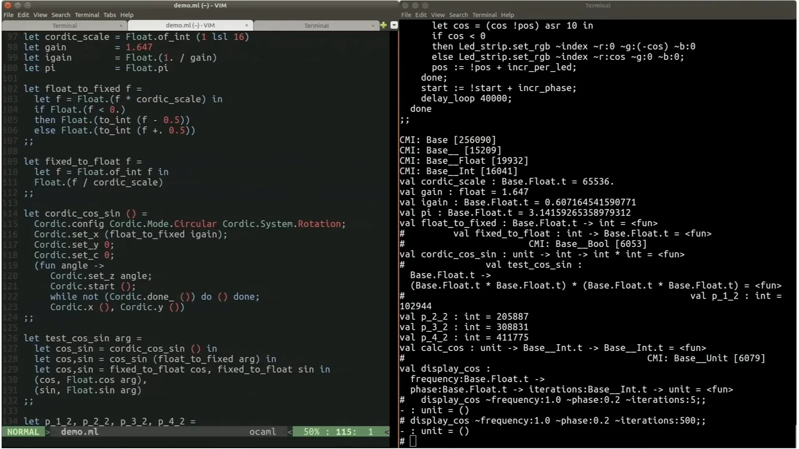
The cosine values appear on the LEDs, with color distinguishing positive and negative values and brightness indicating magnitude. Incrementing the phase moves the waveform across the strip. My favorite demo runs Async on the FPGA: three independently moving colored strobes cover different ranges, while a fourth task halves intensities to create trails.
At the time of the talk, I expect a substantially improved HardCaml release in the Jane Street repositories within a day or two, particularly with more testing. I hope to release older waveform tools, the step test bench and the MicroBlaze simulator later. The demo code needs cleanup, and packaging the cross-compiled C dependencies for OPAM is a difficult part of making it available.
Questions and answers
The audience asks about soft CPUs, direct bytecode execution, Unix, generated Verilog, Bluespec, RISC-V and solvers. Ray explains practical tradeoffs and potential future work.
An audience member asks whether the software runs on a processor implemented in the FPGA. Yes: MicroBlaze is a five-stage RISC soft CPU. The board used here has no hard processor; where an FPGA does have one, I would use it. The soft CPU is for administrative or debugging work, not the hot path.
Asked about executing OCaml bytecode directly in hardware, I say I previously built a state machine capable of running about three quarters of the Caml bytecode VM, in the HardCaml Zinc project. I would like to finish it, but much of Caml is still implemented in C, so a RISC CPU is needed as well.
An audience member asks what I mean by no Unix. The Unix module handles files and networking, but this soft CPU has no filesystem. The design does have a network interface that I have not yet got working; Unix-style sockets would need an emulation layer, and we would probably use lower-level APIs instead.
HardCaml describes a hardware graph in memory on the PC, then generates Verilog for the backend tools. It is not simply running the design as bytecode. A drawback is that the generated Verilog is hard to read, and retaining useful names through to the netlist for timing closure requires care.
Asked about Bluespec, I explain that HardCaml stays close to the abstraction level of Verilog and VHDL; it does not infer a microarchitecture in the way Bluespec can. I like Bluespec's ideas, although I have only read papers about it, and we are considering a DSL above HardCaml that models atomic actions.
For timing problems, the architecture matters. HardCaml generates Verilog corresponding closely to the design the engineer wrote. Naming each register in the HardCaml design makes timing reports understandable as paths from one named element to another, though the generated Verilog itself remains difficult to read.
I would like to replace MicroBlaze with RISC-V. Beyond personal interest, controlling that part of the technology could make upgrades and compiler management easier than depending on large vendor toolchains that change frequently.
The interactive top level on a small board is partly for fun, but soft CPUs do have practical uses in our designs. Some embedded code, such as a kill switch, can be critical and needs review. The team knows how to review OCaml, whereas introducing a large amount of C is less comfortable. An interactive top level could also help early debugging by letting engineers inspect registers.
Finally, asked about solvers, I say I am currently using SAT tools, principally MiniSat, rather than SMT. Z3 and its OCaml bindings have recently entered the repository, and I would like to experiment with them when I have time.
같은 채널의 다른 글
 15:33EN
 1:48:29EN
 1:36:37EN
 1:05:45EN
 1:25:00EN
 1:16:29EN